Verification of the Impact of Clamp Types on the Thermal Runaway Test Results of HWS Batteries
This study employs standard samples with diverse clamp types and a calorimeter calibration device to simulate adiabatic thermal runaway experiments for High-Temperature Safety (HWS) batteries. It explores how different clamps affect battery thermal runaway characteristics and adiabatic temperature rise test outcomes, aiming to advise users on optimal sample clamping techniques.
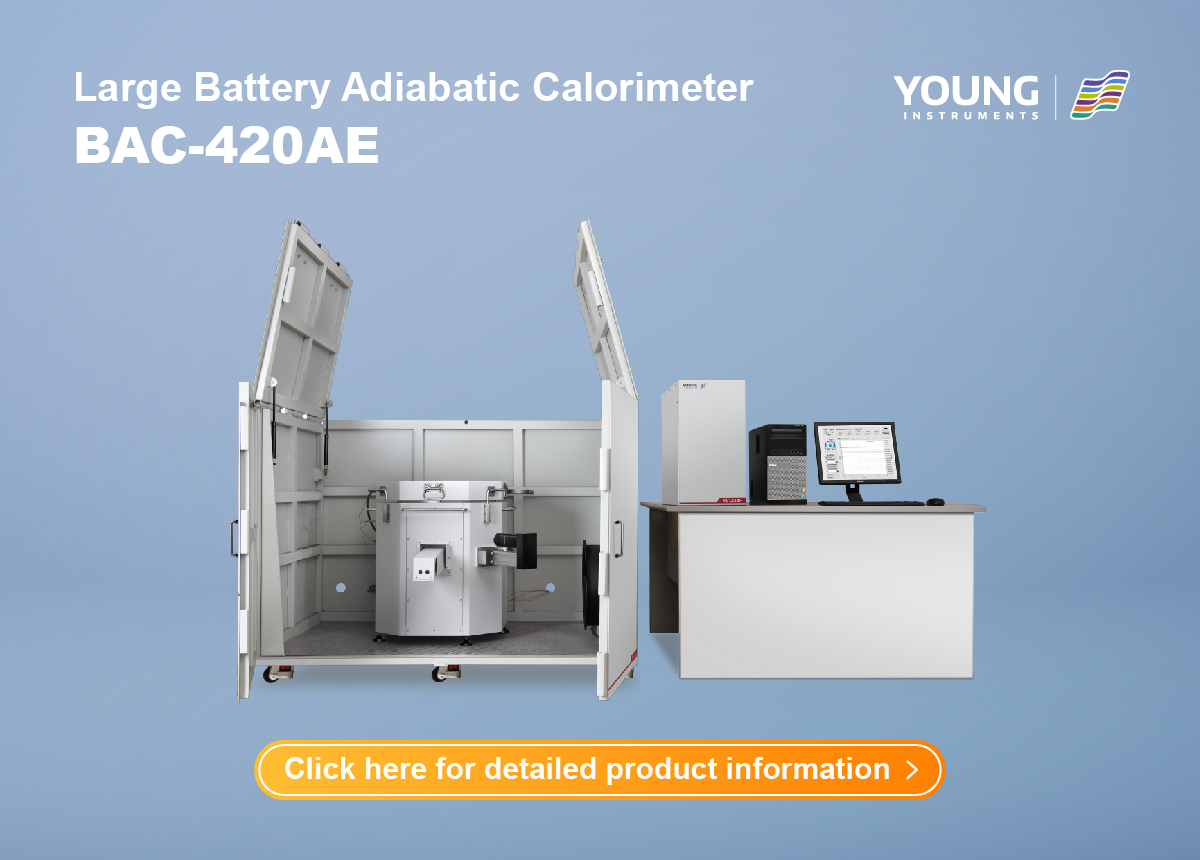
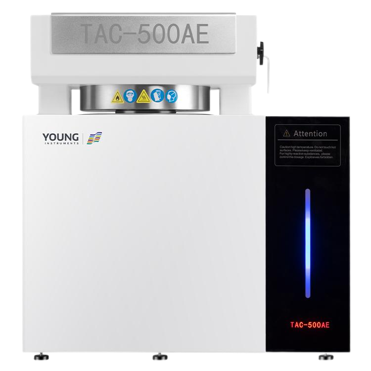
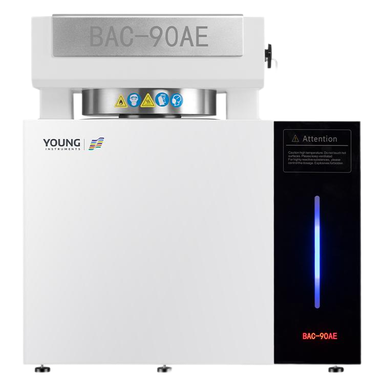
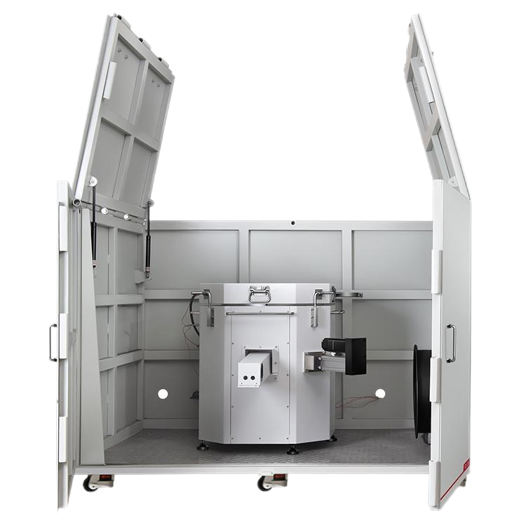
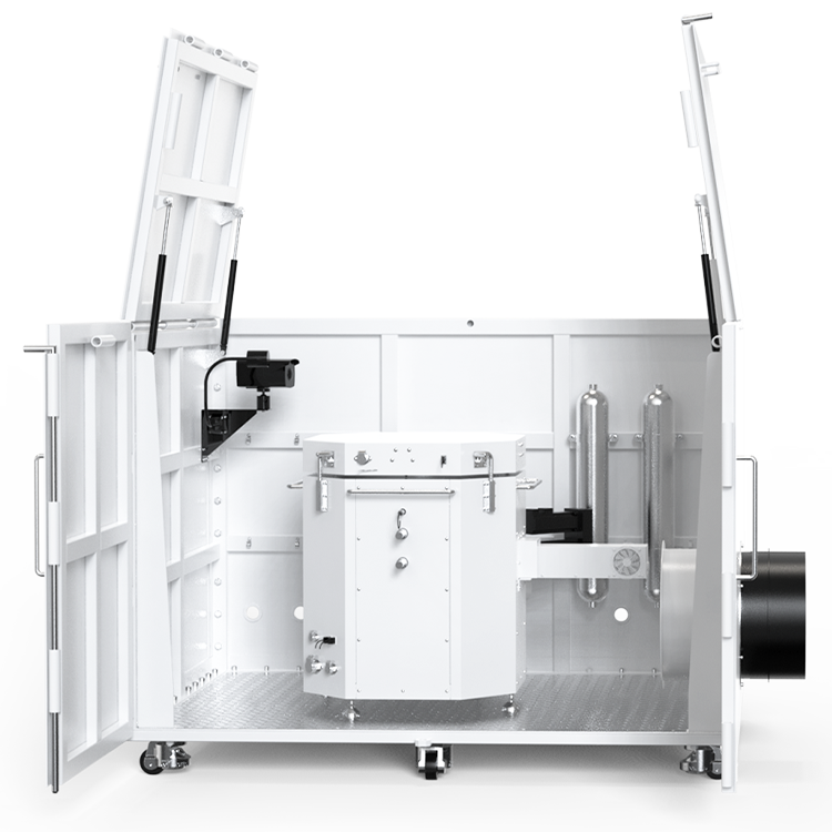
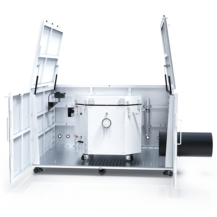
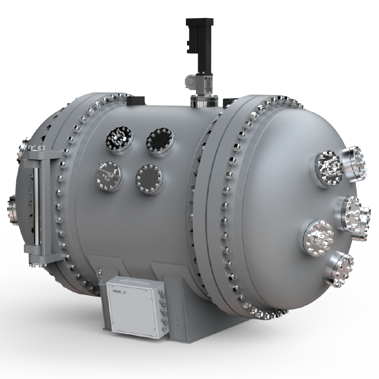
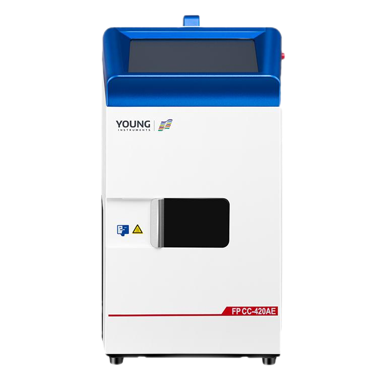
Figure 1: Large Battery Adiabatic Calorimeter BAC-420AE
Introduction
Avoiding lithium battery thermal safety risks requires obtaining thermal characteristic parameters to design protective measures and early warning systems. The industry primarily uses an Accelerating Rate Calorimeter (ARC) to test lithium batteries’ key thermal parameters. This device measures self-heating characteristics under adiabatic conditions, providing data on thermal runaway or temperature rise (GB/T 36276-2023).
In the experimental process, batteries often swell due to internal gas production at high temperatures. Clamps are typically used to secure temperature sensors, preventing measurement anomalies from sensor detachment or poor contact, thus ensuring data accuracy. However, clamps have thermal inertia that can absorb heat from the battery, potentially leading to underestimated temperature rise rates and delayed detection of key temperatures, such as the self-heating onset (Tonset).
This study employs a battery calorimeter calibration device to scientifically assess the impact of various clamps and installation methods on battery thermal runaway and adiabatic temperature rise characteristics. By simulating the thermal runaway temperature rise curve of a specific ternary lithium-ion battery, we evaluate the detection errors in the sample’s self-heating rate.
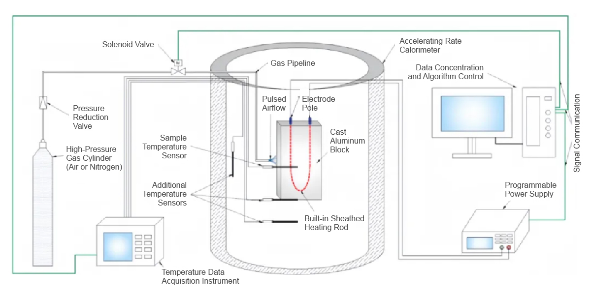
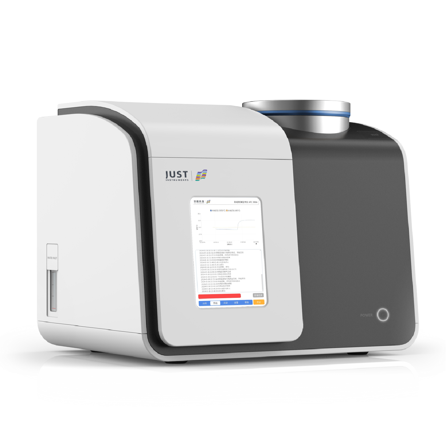
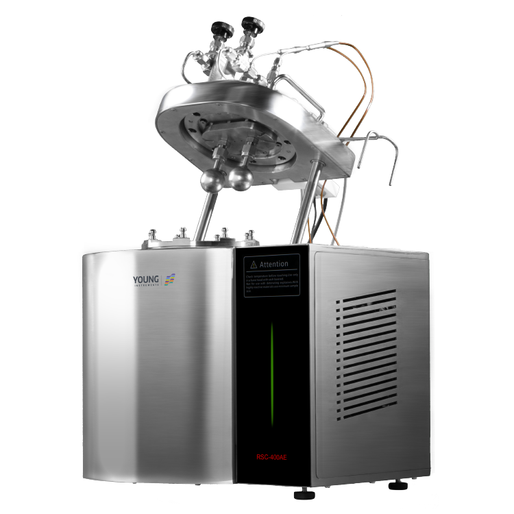
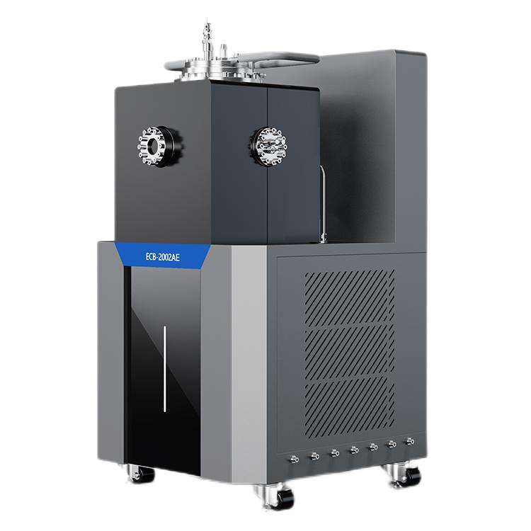
Figure 2: Battery Adiabatic Calorimeter Calibration Device
Experimental Results
Without Clamp

Figure 3: Standard resistance block without clamp
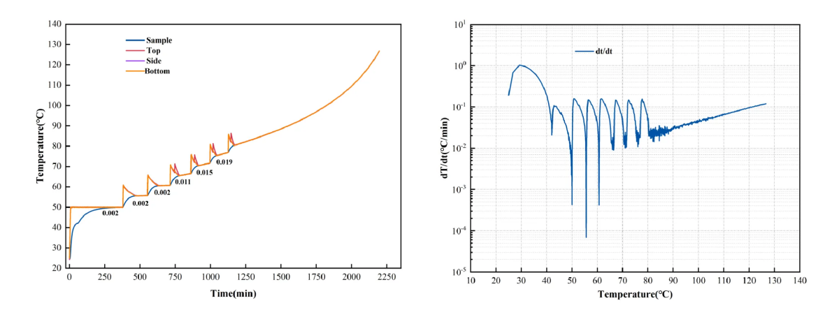
Figure 4: HWS temperature rise (left) and temperature rise rate-temperature (right) curves of the standard resistance block without clamp
Metal plate clamp
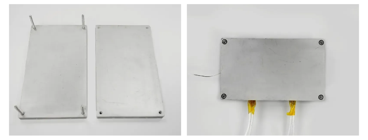
Figure 5: Sample preparation with metal plate clamp
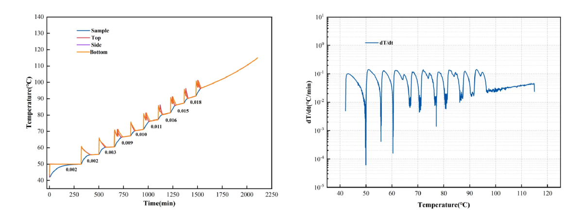
Figure 6: HWS temperature rise (left) and temperature rise rate-temperature (right) curves of the standard resistance block using a metal plate clamp
Metal plate clamp with built-in heat insulation tape
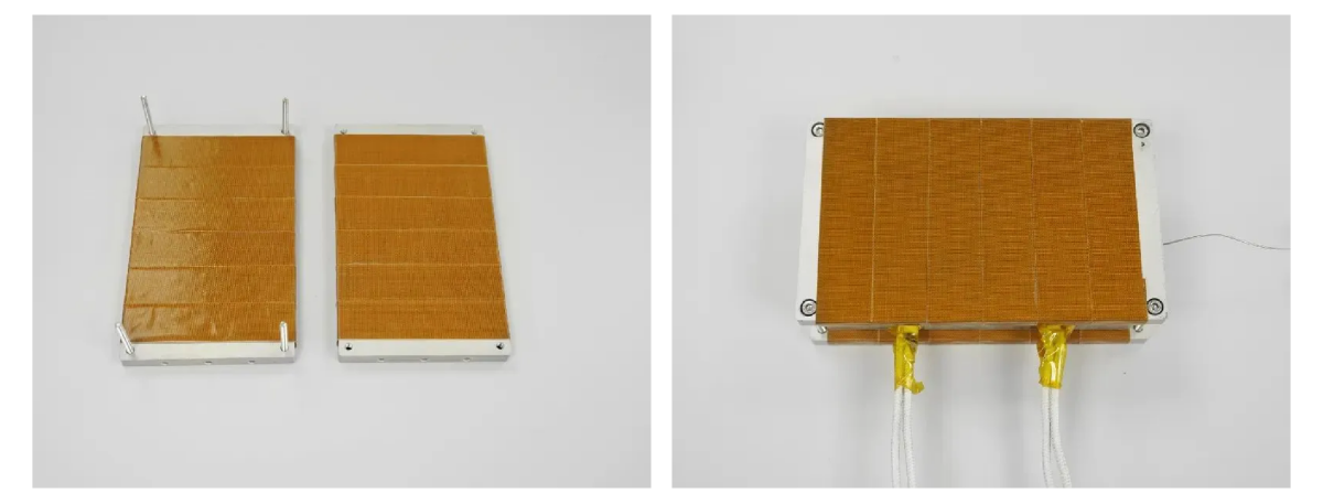
Figure 7. Sample preparation with metal plate clamp featuring built-in heat insulation tape
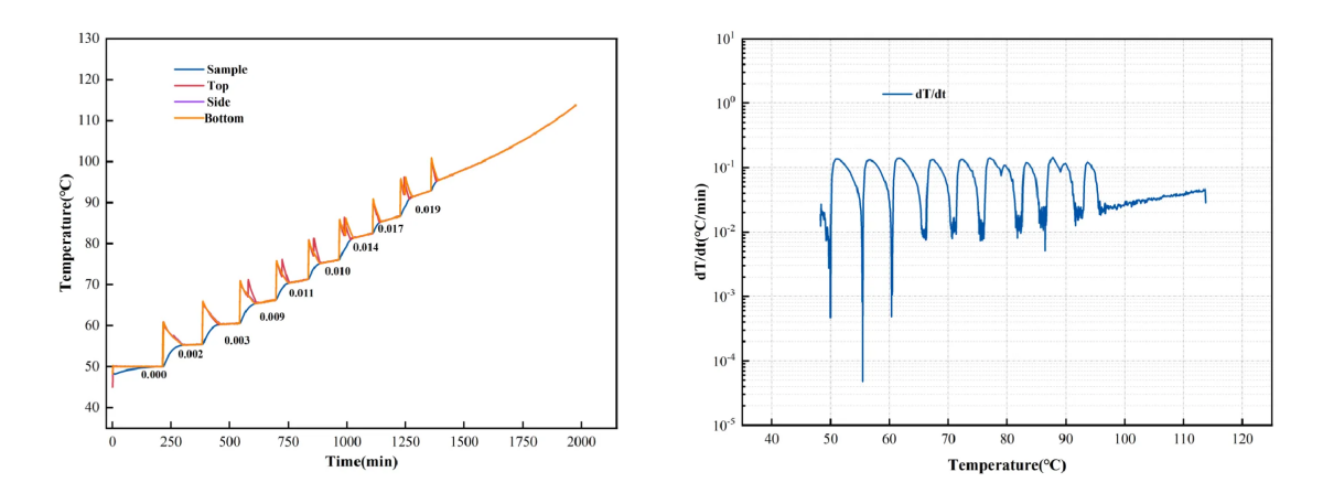
Figure 8. HWS temperature rise (left) and temperature rise rate-temperature (right) curves of the standard resistance block with a metal plate clamp equipped with built-in heat insulation tape.
Metal plate clamp with thermal insulation cotton layer
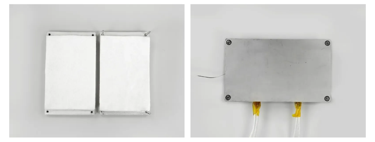
Figure 9. Sample preparation with metal plate clamp featuring a thermal insulation cotton layer
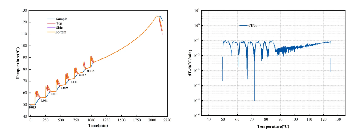
Figure 10. HWS temperature rise (left) and temperature rise rate-temperature (right) curves of the standard resistance block using a metal plate clamp with a thermal insulation cotton layer. 05 Steel rib clamp.
Steel Rib Clamp
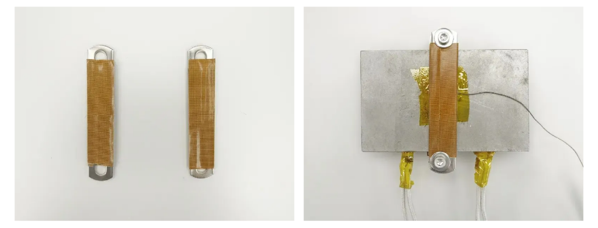
Figure 11: Sample preparation with a steel rib clamp
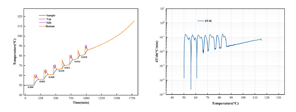
Figure 12: HWS temperature rise (left) and temperature rise rate-temperature (right) curves of the standard resistance block using a steel rib clamp.
Further comparison of the standard sample temperature rise rates measured under different clamping methods is shown in Table 1:
Table 1: Comparison of Adhesive Temperature Rise Rates of Standard Samples in the Adiabatic Tracking Stage under Different Clamping Methods
|
|
Tonset/℃ |
dT/dt/(℃/min) | ||||||
| 85℃ | 90℃ | 95℃ | 100℃ | 105℃ | 110℃ | 115℃ | ||
|
Without Clamp |
82.17 |
0.023 | 0.030 | 0.037 | 0.045 | 0.055 | 0.066 | 0.080 |
|
Metal plate clamp |
98.44 | – | – | – | 0.027 | 0.033 | 0.038 | 0.046 |
|
Metal plate clamp with built-in heat insulation tape |
97.29 | – | – | – | 0.026 | 0.031 | 0.037 | 0.046 |
|
Metal plate clamp with thermal insulation cotton layer |
87.78 | – | 0.024 | 0.028 | 0.033 | 0.040 | 0.047 | 0.058 |
|
Steel Rib Clamp |
87.70 | – | 0.026 | 0.032 | 0.040 | 0.050 | 0.061 | 0.076 |
By comparing the temperature rise rates of standard samples across various steps, Tonset detection temperatures, and temperature rise rates at different temperatures during the tracking phase under diverse experimental conditions, we conclude the following:
- Figures 4, 4, and 12 show that adding clamps to the standard resistance block leads to some heat absorption, resulting in a slight delay in the ARC-detected Tonset temperature. This delay correlates with the clamps’ thermal capacity. While steel rib clamps with lower Phi values minimally affect temperature rise rate measurements, selecting the right clamp can keep deviations below 0.005°C/min, ensuring acceptable Tonset test outcomes.
- Comparisons shown in Figures 6 and 8 indicate that commonly used heat insulation tapes, like Teflon, provide minimal insulation during experiments and do not significantly reduce the thermal inertia (Phi value) of the clamps.
- .Figures 4, 6, and 10 demonstrate that inserting heat insulation cotton between the battery and the metal plate clamp offers some insulation, markedly reducing heat transfer. However, it cannot achieve full heat insulation. Thus, the thermal inertia of metal plate clamps may still affect test outcomes.
To reduce the impact of clamps on test results, it is advised to use steel rib clamps with lower thermal capacity for securing thermocouples and to insulate the clamps from the battery using heat insulation cotton.
Conclusion
This study used the BAC-420AE large battery adiabatic calorimeter and a calibration device to simulate thermal runaway experiments. It assessed the effects of various clamping methods on the detection of sample self-heating. The findings suggest that for High-Temperature Safety (HWS) adiabatic thermal runaway and temperature rise characteristic experiments, using steel rib clamps with lower thermal capacity is preferable. This choice enhances the accuracy of thermodynamic parameter testing.


